FOAM Zone Anchor
Date
2021-2023
Team
Adem Onalan, Cody Moore, Marco Perry
Tags
Mechanical Engineering | Mechanical Design | Industrial Design Integration | Ingress Protection | Production CAD | Thermal Analysis | Validation and Testing | Component Sourcing | Contract Manufacturing Liaison
Project Highlights
Overview
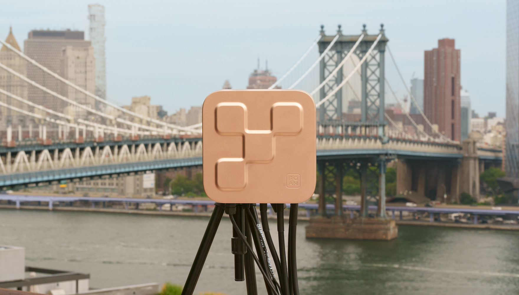
The Zone Anchor is the flagship product in a network of devices enabling decentralized location services. As a startup entering a developing market, the client was looking for a compelling design to communicate their brand values and connect with early adopters and enthusiasts.
As lead mechanical engineer, I translated the industrial design vision into a manufacturable product—balancing usability and aesthetics with the functional and performance requirements for an outdoor device.

Mechanical Design
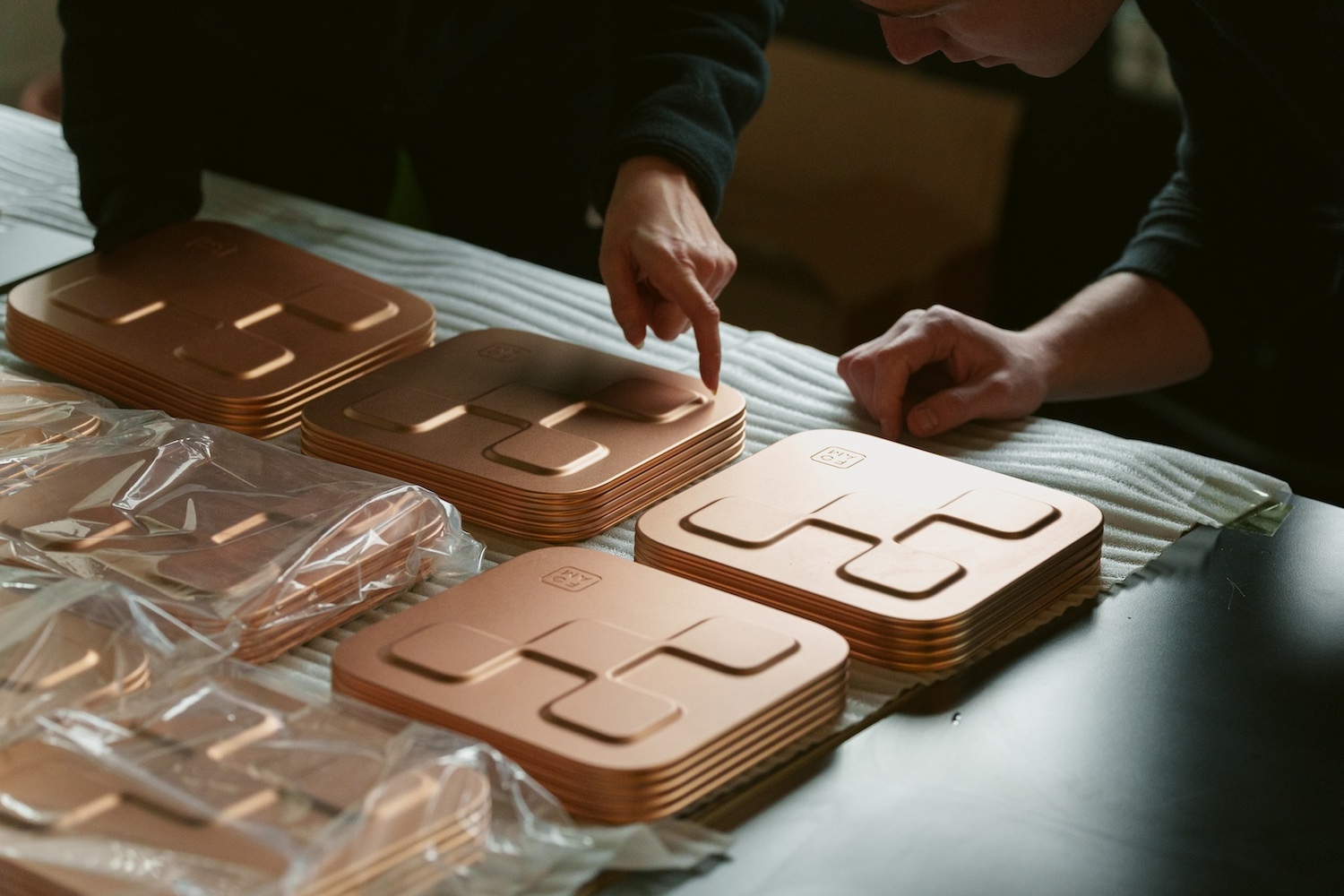
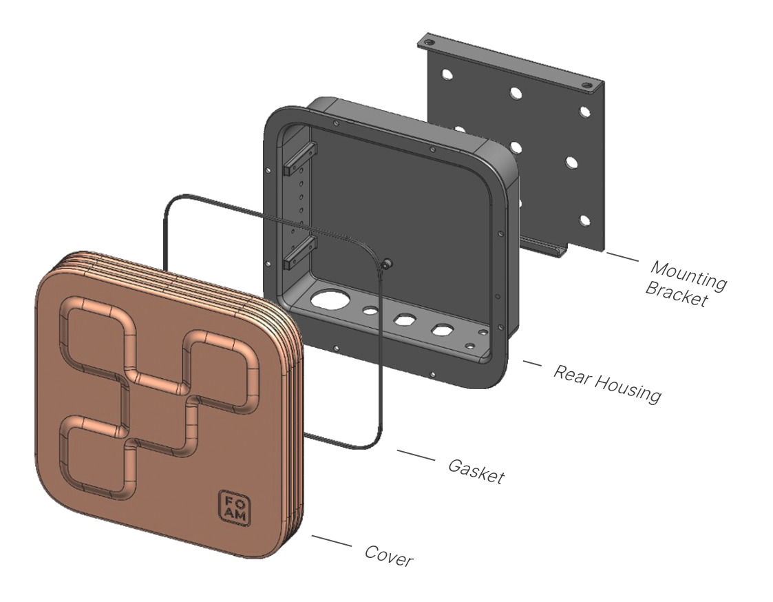
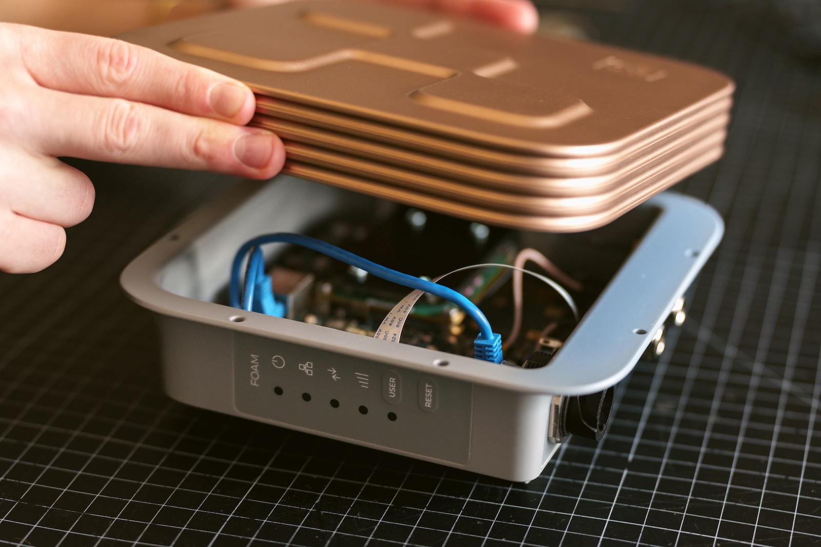
The enclosure is a three-piece construction consisting of the Cover, Gasket, and Rear Housing with an external Mounting Bracket.
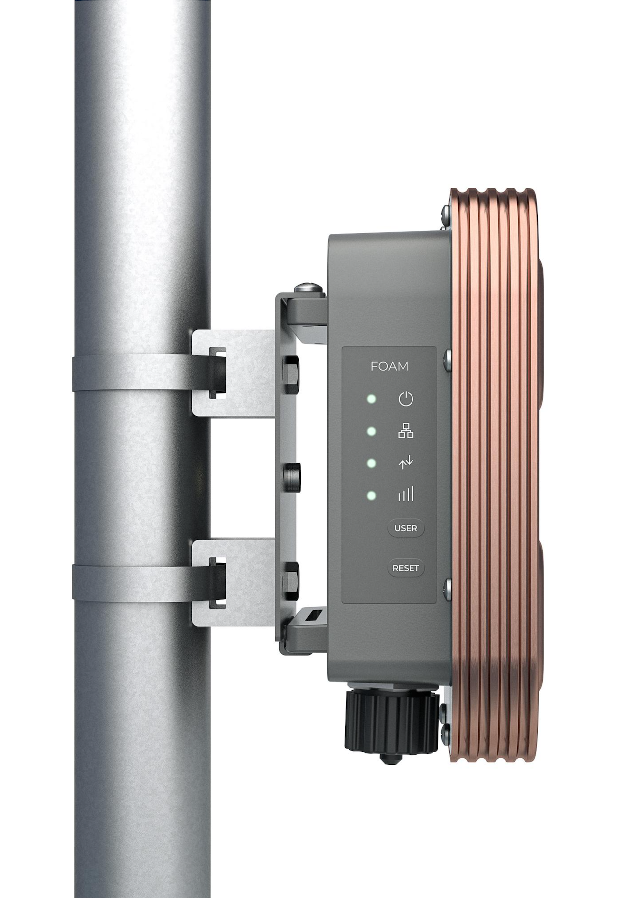
The Cover is a machined aluminum part. Being highly cosmetic, a bead-blasted, anodized finish was chosen. A custom Gasket fits within a groove in the Cover, providing a watertight seal. The Rear Housing is another machined aluminum part with mounting features for the PCBAs, panel-mount connectors, and graphic overlays. The Mounting Bracket is a bent sheet metal part made from stainless steel, and offers several standard mounting options for roof-mounted equipment.
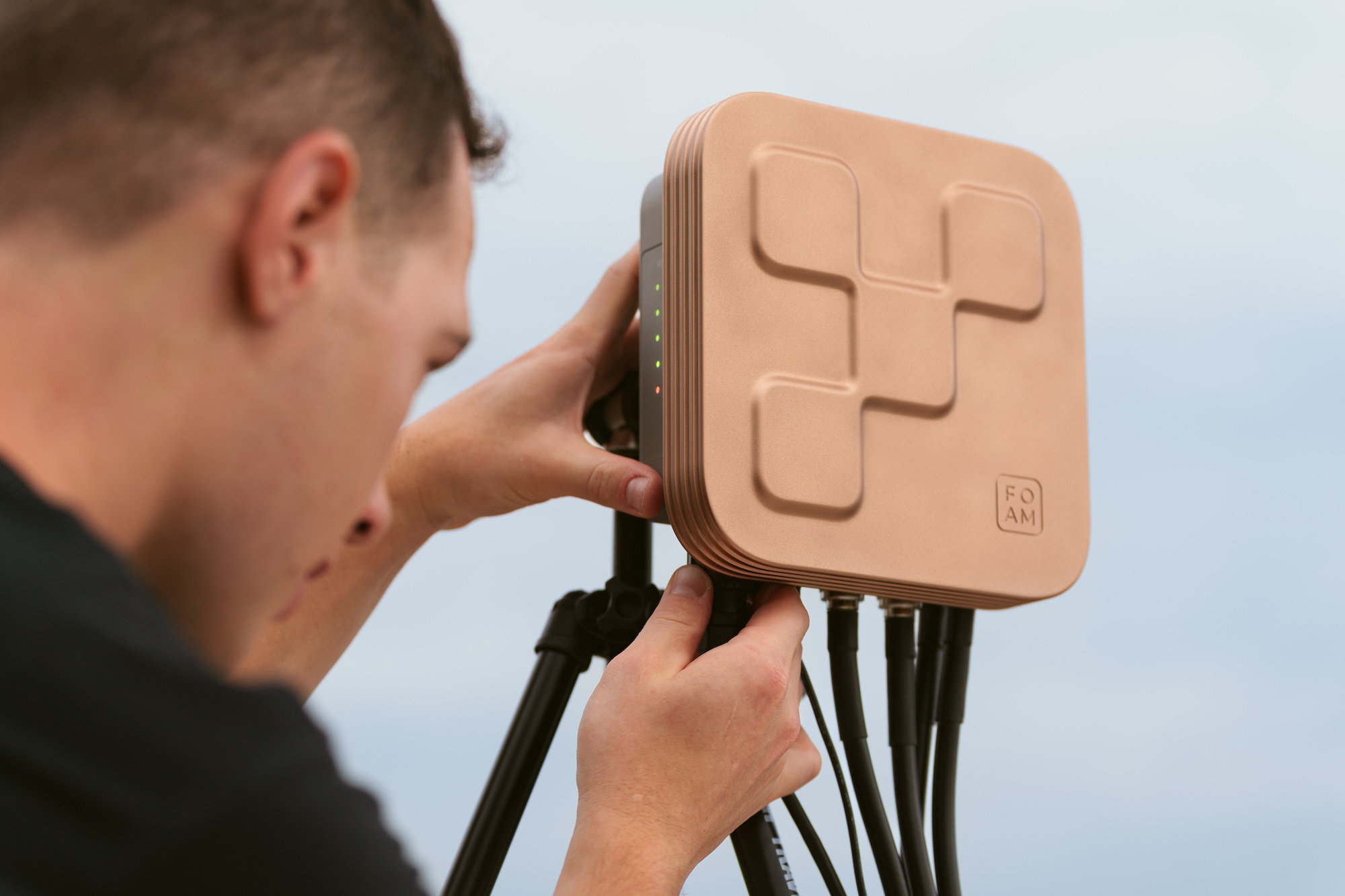
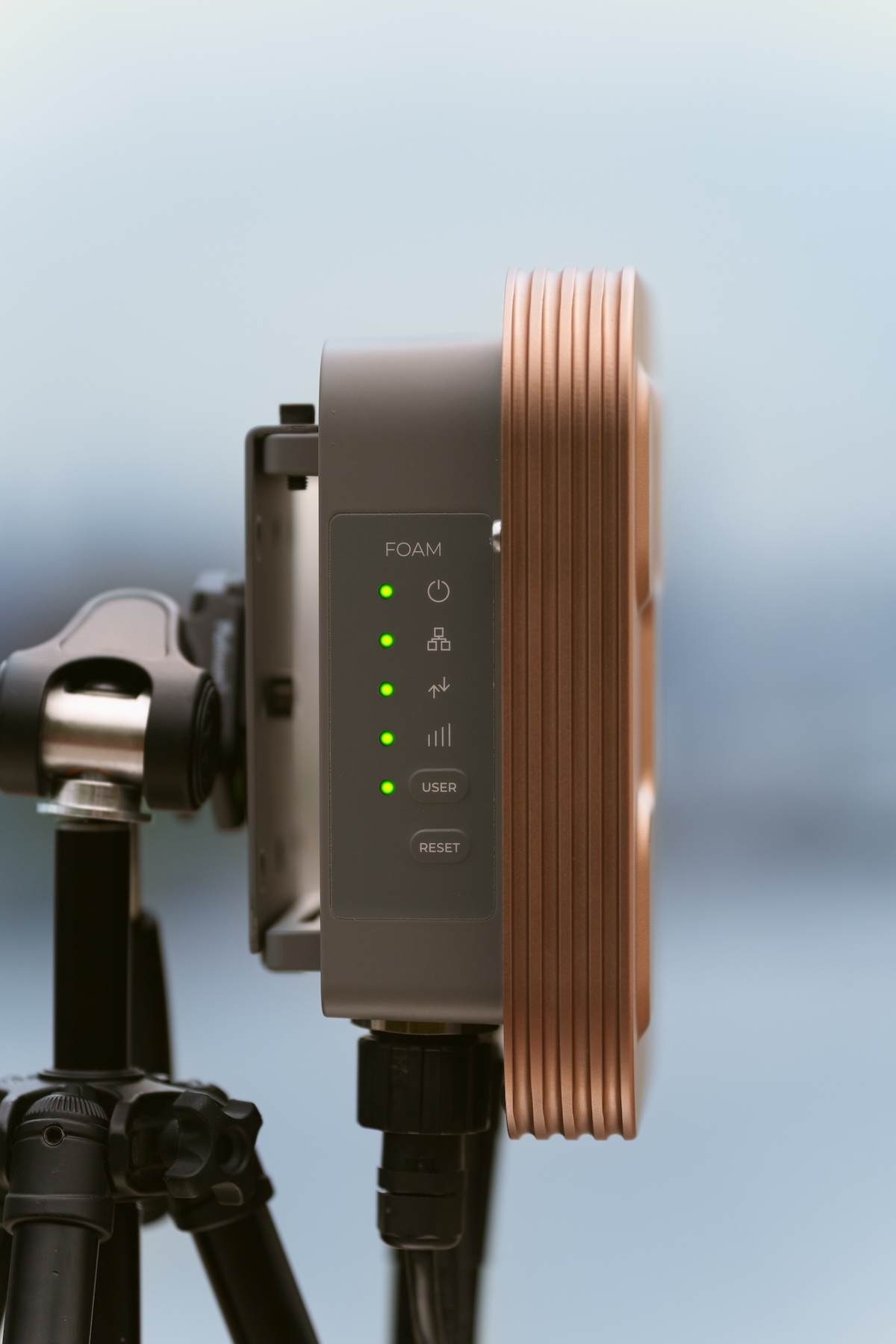
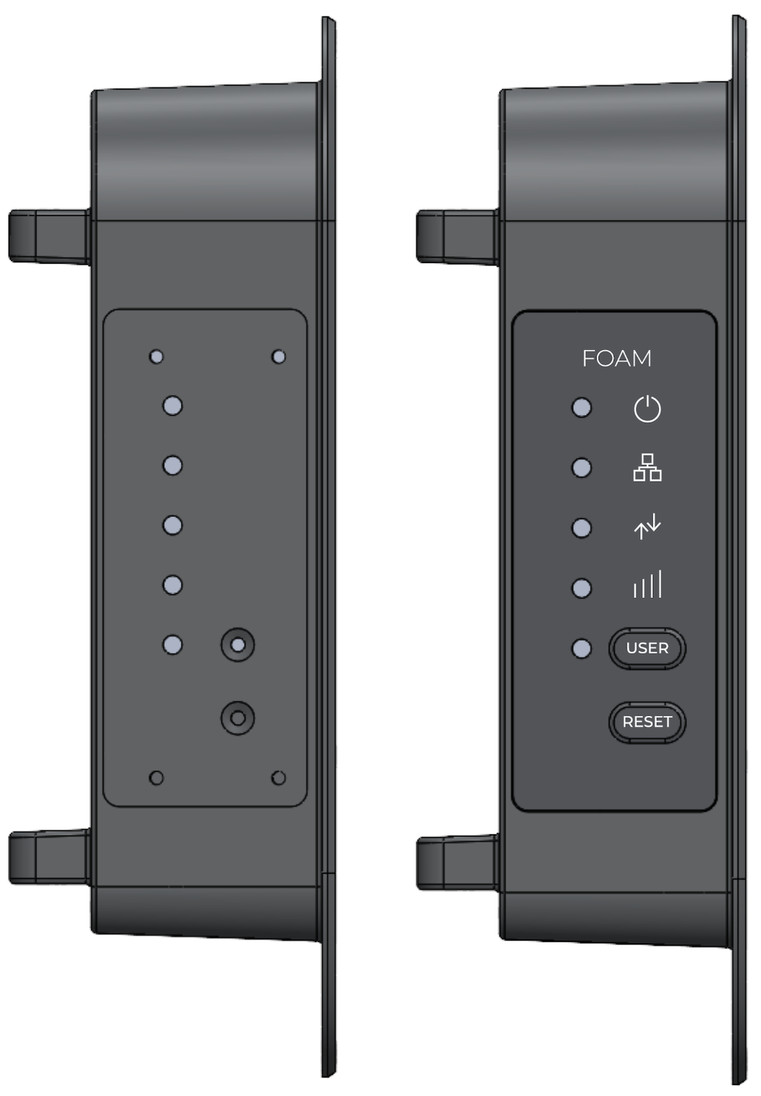
The size of the device was primarily driven by the space requirements of the I/O components. We positioned the I/O components that would see more frequent user interaction (status LEDs and buttons) on the side of the Rear Housing, and inset their position to discourage unauthorized use of the device. Doing this also allowed the Cover to remain the focal point of the product.
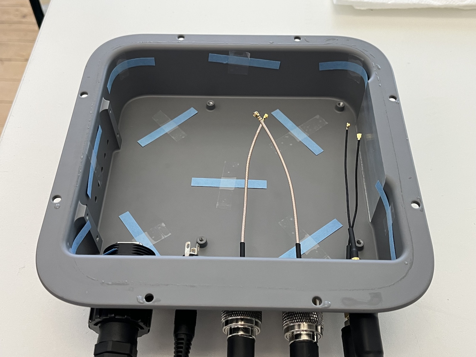
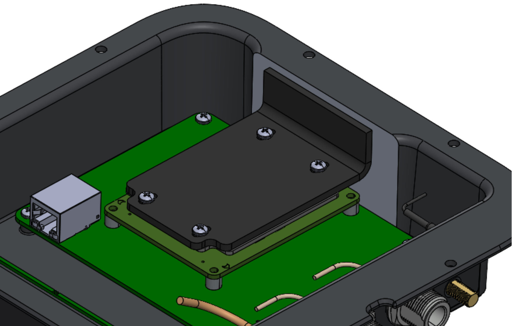
The enclosure is designed to house two PCBAs, a custom heat spreader, six panel-mount connectors,buttons, LEDs, and a custom cable harness. Engineering considerations were made for waterproofing and heat dissipation to ensure reliable performance outdoors.
Ingress Protection
Several provisions were made for ensuring a watertight enclosure.
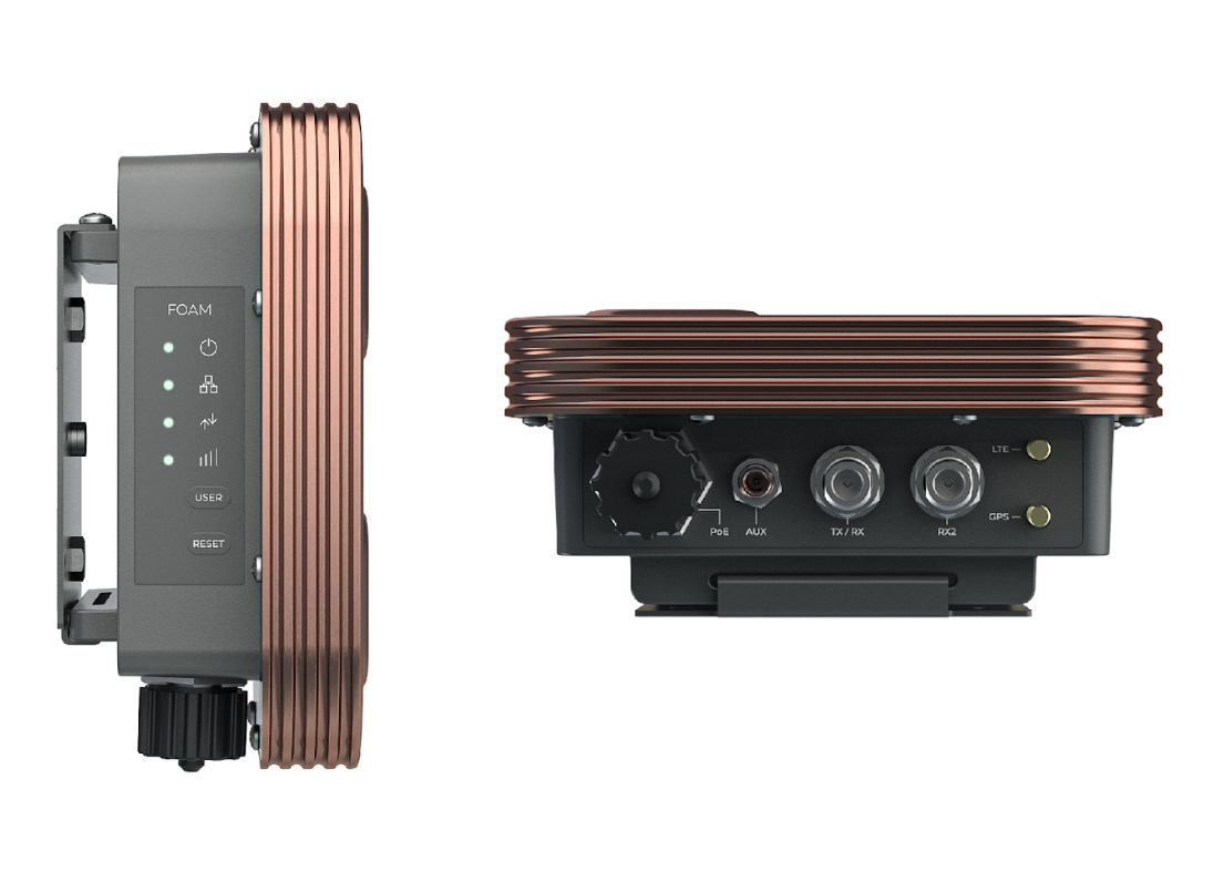
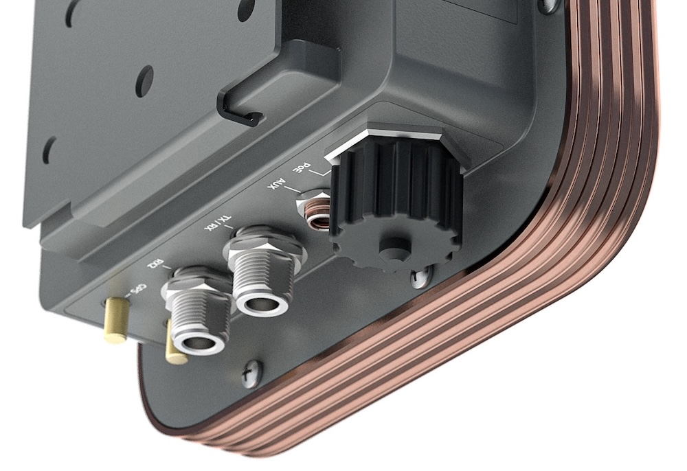
We sourced IP-rated connectors and positioned them on the bottom face of the Rear Housing. This minimized the risk of water ingress from water pooling on the top flat surface.
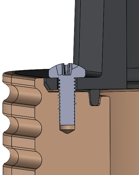
A custom gasket was integrated around the cover's mounting screws to prevent ingress through the screw holes.
We also designed waterproof polyester graphic overlays with adhesive backing to seal additional ingress points like screw bosses and passthru holes for the LEDs.
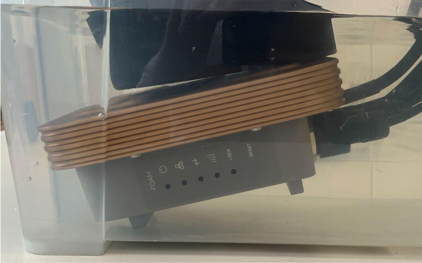
For initial validation of the waterproof design, we performed testing comparable to IP67, fully submerging the assembled enclosure for 30 minutes and using moisture detection strips to confirm that no ingress was observed.
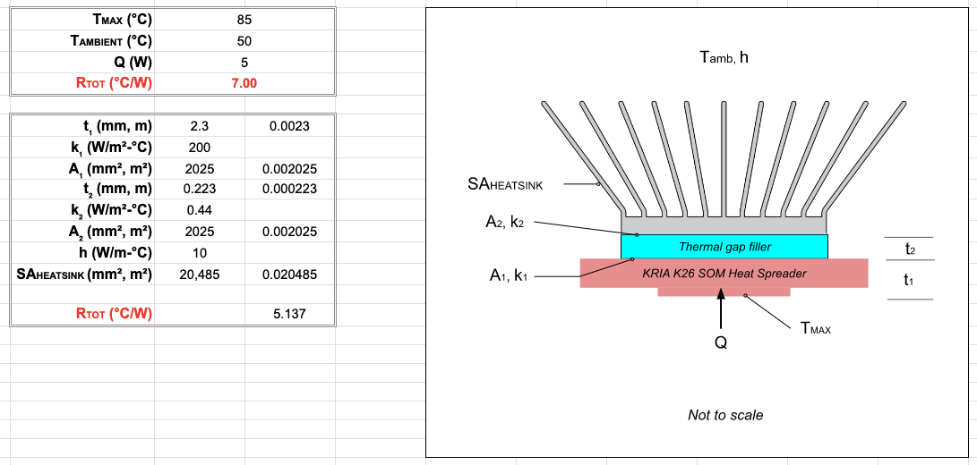
Thermal Analysis
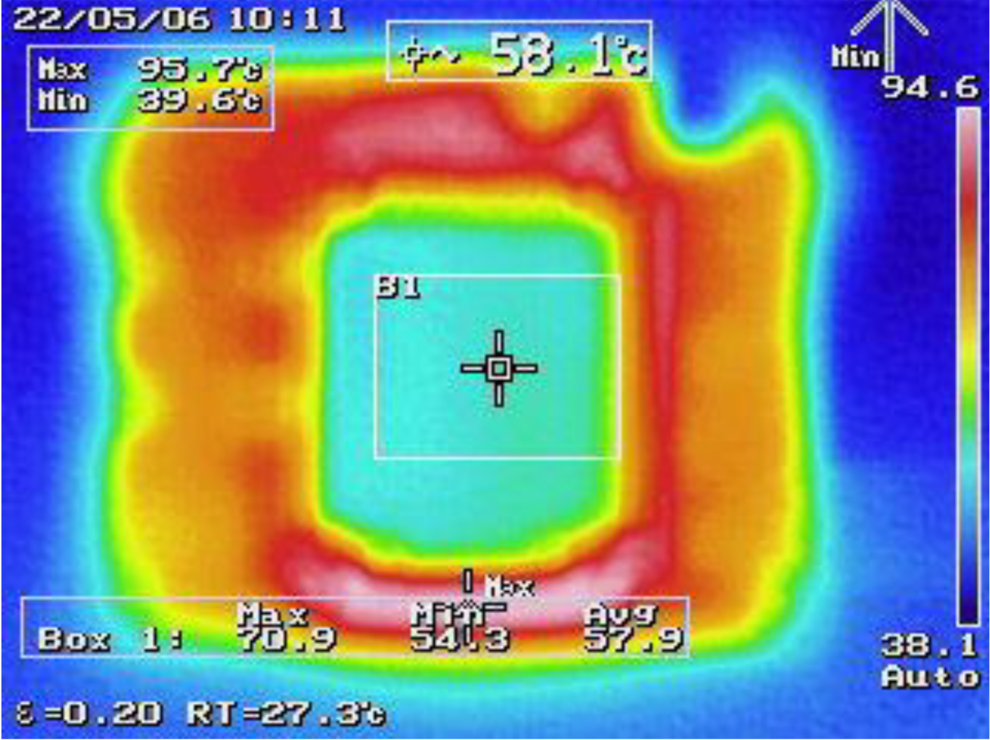
Thermal testing by the electrical team revealed a need for additional thermal management, and my calculations and simulations confirmed that passive cooling with a heatsink would suffice. I validated this using an off-the-shelf aluminum enclosure with similar material, shape, and thickness.
I designed a custom bent aluminum heat spreader to transfer heat from the main compute module to an inner wall of the Rear Housing, effectively transforming the entire Rear Housing into a heat sink
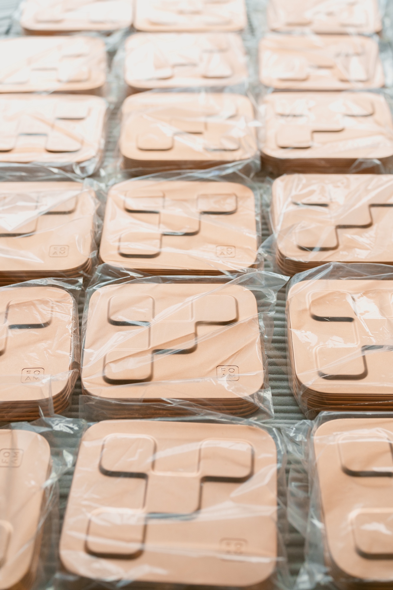
Pilot Run Production
In addition to mechanical design and engineering, I managed the pilot run production efforts for 100 units. This involved building a top-down parametric model of the enclosure, as well as creating engineering drawings, maintaining revisions, and managing the mBOM.
I sourced components and worked with an overseas contract manufacturer to produce the enclosure, graphic overlays, and custom wire harnesses. I also managed the project timeline and presented regular progress updates to our client.